🚗 Drive Your Innovations Forward!
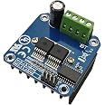
The HiLetgo BTS7960 43A High Power Motor Driver Module is designed for Arduino enthusiasts, providing a powerful and efficient solution for controlling motors. With features like bidirectional control, real-time voltage monitoring, and a wide voltage range, this module is perfect for smart car projects and other high-demand applications.
J**E
BTN7960B Motor Driver
This is a very affordable and cost effective solution for driving large DC motors via PWM. I did a lot of research and found the Infineon single bridge IC's were the best sporting dual FETs and a driver all in 1 IC package! They have newer model ICs that support up to 70A spikes and 50A continuous but nobody has made a mass produced cheap module like this one. Searching for the Infineon IC model BTS7960B (Really BTN7960) will bring up this IBT-2 motor driver from everywhere. I would like to see the BTN8982 IC mass produced like this.Anyways, this IBT-2 motor controller also has a 74HC244 Octal buffer which isolates your Arduino/PIC/Arm microcontroller from the Infineon ICs. Good protection. Each IC can either drive 1 motor in 1 direction (2 Motors total -> One way) -or- you can combine them to form an H-Bridge and control 1 motor bi-directionally (Forward and reverse). I like configuration #2. If you are going to use this in H-Bridge mode, you must have the enable pins on BOTH ICs active. 1 IC will drive your + side, the other will be the - side and so both IC's must be enabled to conduct. Send a PWM signal @ 1khz-25khz to either IC to drive your motor in that direction. You will have to work out the logic to make sure you are PWMing on 1 input at a time.Last but not least I ordered 2 of these controllers and one of them came with mistakes, really bad mistakes. Like its gonna smoke and sizzle if you were to just plug it in and use it. Both ICs had obvious solder bridges between different sets of pins. These were not ground pins. One pair was Inhibit -> OUTPUT. The other bridge was OUTPUT -> Slew Rate. The chip was also skewed to the point where the slug(output) was a micrometer from the left ICs output. They were almost touching each other. Had to do some rework which I love doing anyways :). Pictures attached. I added solder to fill in some vias for heat transfer to the radiator. Also added some thin ceramique paste for the radiator. The solder pad on the left is OEM...not much solder in them vias. There is a "Too Much" limit though. You don't want the heat IN the solder, just transfered.
D**S
Great for the money
Limited voltage use, about 8 to 22 volts. If this is ok it is a fine driver. I am using 3 to drive 3-phase magnet coils and they are fine. I bought several in case there was a problem. No problems connecting or using them. I recommend them.
M**E
Low heat thanks to MOSFETs — Serious but fixable manufacturing flaws — Hints on PWM frequency
Summing up — This module produces much less heat than competing designs not using MOSFETs. But beware of a potential short-circuit you need to check first. And if you aim to use it at high currents you need to address a manufacturing flaw. As for packaging, an earlier and frequent complaint, it now comes in a sturdy little box at least from this supplier. No more bent pins.MOSFET H-bridges such as the BTS7960 generate much lower heat than more common designs built around BJTs such as the L298. But whatever heat gets generated goes somewhere. Here it flows by way of tiny thru-holes called vias to a large heatsink bolted to the back. These vias are supposed to be filled with solder to provide thermal conductivity. A cute approach, but my module contained only 2 out of 60 intact thermal vias. See photo. This is a serious manufacturing flaw rendering the heatsink completely useless.The second flaw is a potential short. The anodized surface of the heatsink is very thin. This surface broaches easily and can short out the motor terminals because the two chips' metal casings are internally connected to the two output poles. You need to check this before first use.As for the heatsink, at lower currents you can remove the heatsink altogether. I did this for a 4A-25W application running at 25kHz PWM frequency.* Hardly any heat. So try this first. You can use the chips as guide because they shut down in case of overheating. This approach takes care of both issues.But if heat is an issue then you have to make repairs. Gently scrape the lacquer off the rectangular areas. Drill out the holes to a slightly larger diameter, if you have those skills. Cover the now bare copper surface with solder, making sure to fill up all the vias and keeping the solder surface as level, thin and smooth as possible. Then remount the heatsink with a thermal pad in between to provide electrical insulation, again taking care of both issues.Note that the 43A current limit is lifted from the chips' spec sheet. It requires sufficient cooling. It seems unlikely that even perfectly filled-in vias provide enough heat flow to achieve this number before overheating but it's worth a try. A next step would be to cut out the via rectangles altogether and use perfectly flat copper shims instead. Do remember the electrical insulation.Addressing the module is straightforward. There are plenty of videos and written application notes to show you how. Control signals are wired up with 2.43mm pitch DuPont connectors. The signal pins are marked well. All signals are buffered for isolation and safety.The screw-type terminals on the power side are solid and adequately sized.Summing up, the major advantage of designs based on MOSFETs is very low heat loss. Indeed, at lower currents this module can be used without a heatsink. And this is a sophisticated chip with built-in overcurrent and overheating protection. Buffering its well-marked control and monitoring signals is an elegant touch. The price is very low for a device with this potential. And you can use it at higher currents after a fix. Subtracting one star for manufacturing flaws._______________* There is an excellent free Arduino library that allows PWM frequencies into high kHz range. (Arduino's standard analogWrite operates around 500Hz.) High PWM frequencies lead to smoother running and eliminate whine with somewhat more switching heat. It’s all a balance. Amazon does not allow external links in its reviews so look for pwm-frequency-library in the official Arduino forum.
T**S
Trash, not as advertised, CLONES NOT UL STAMPED, BAD SOLDER, CROOKED PINS, NOT 43A
They sent clones, the components were crooked to the point they shorted out, and they do NOT take 43A. Im guessing thats a number from bench tests in PERFECT testing conditions, and even then probably burst rating rather than sustained. Garbage, do not buy.
G**E
Excellent motor controller for Arduino setup
I’ve had no issues and used a few of these controller so far. Currently 2 are running automated gates and have been cycled hundreds of times without failure.
M**2
Prompt shipping and it works fine!
HiLetgo contacted me (email) the day the part arrived, was it functional and was I satisfied? Yes to both so I can't comment on their customer service. I've only tested the driver under light loads (<2A) and it works great. Other reviews suggested inspecting the driver before applying power, which is a good idea regardless, and I found several tiny solder balls lurking behind pins of the BTS7960 ICs. The driver was shipped in a padded mailer, encountered some rough handling and several header pins got bent (straightened with pliers). Other comments: mine arrived with no documentation (easy to find, just search IBT-2) and "the supply voltage 5.5V to 27V." means motor (load) voltage range. It will not work with 5V. Yes, I would buy more.
Trustpilot
4 days ago
2 months ago
![Arduino Uno REV3 [A000066]](https://images-na.ssl-images-amazon.com/images/I/61AvdQOxFzL._AC_UL116_SR116,116_.jpg)