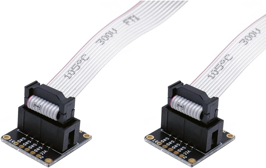
2pcs JTAG Breakout Board Adapter SWD Adapter Board Jtag Debug Board with 2 Row 2.54mm Pitch 10pins Female to Female IDC Connector Flat Flexible Gray Ribbon Jumper Cable 200mm Pitch for J-Link
Product ID: 378938972
Details
- BrandTreedix
- ColourGrey
- Connector typeUsb
- Item weight0.03 Kilograms
⚡300V withstand voltage
📏20cm flat ribbon cable length
🔌10-pin 2.54mm pitch connector
Buy anything from 5,000+ international stores. One checkout price. No surprise fees. Join 2M+ shoppers on Desertcart.
₨664
1
Sold byAmazon SeychellesDelivered byDesertcartCustomer service byDesertcartReturns14 days · 30 with PRO
Buyer Protection · Full refund if your order doesn't arrive as described.
Desertcart purchases this item on your behalf and handles shipping, customs, and support to Seychelles.
Secure transaction
Details
- BrandTreedix
- ColourGrey
- Connector typeUsb
Description
🔧 Debug Like a Pro — Connect, Code, Conquer!
- PRECISION 2 54 MM PITCH - Industry-standard 10-pin spacing ensures perfect fit and reliable connections every time.
- SEAMLESS ARM DEBUGGING - Plug-and-play adapter compatible with ARM-USB-OCD and J-Link for hassle-free circuit programming.
- HIGH VOLTAGE DURABILITY - Supports up to 300V withstand voltage, built to endure demanding development environments.
- FLEXIBLE 20 CM RIBBON CABLE - Generous cable length offers versatile wiring options for complex debugging setups.
- UNIVERSAL JTAG SWD SUPPORT - Works flawlessly with Atmel AVR, Segger JLINK, and other popular debuggers for maximum compatibility.
This 2-piece JTAG breakout board adapter kit features a 10-pin 2.54mm pitch female-to-female IDC connector with a 20cm flat flexible ribbon cable. Designed for ARM-USB-OCD, J-Link, and Atmel debuggers, it enables precise programming and debugging of ARM and AVR circuits. Rated for 300V withstand voltage and 105℃ operating temperature, it offers durable, flexible connectivity for professional-grade embedded development.
Specifications
| ASIN | B09JKBMPKZ |
| Brand | Treedix |
| Color | Grey |
| Compatible Devices | ARM-USB-OCD, ARM-USB-OCD-H, ARM-USB-TINY, ARM-USB-TINY-H, ADA1675 cables, Atmel-ICE PCBA, Segger’s JLINK |
| Connector Type | Usb |
| Customer Reviews | 4.2 4.2 out of 5 stars (10) |
| Item Weight | 0.03 Kilograms |
| Manufacturer | Treedix |
| Model Number | Treedix |
| Number of Items | 2 |
| Number of Ports | 10 |
| Package Quantity | 1 |
| UPC | 764784798620 |
Common Questions
Yes, all products are sourced directly from authorized retailers in the US, UK, UAE and India. We maintain strict quality control processes and verify each product before shipping. All items come with applicable manufacturer warranties and are covered by our standard return policy.
Delivery times vary by destination country, typically ranging from 3-9 business days. Each order is fully trackable through our system. We handle all customs clearance and use reliable courier partners for last-mile delivery. You'll receive regular updates about your order status via email and our app.
Desertcart is an international e-commerce platform operating since 2014. We securely process thousands of orders globally each day. Every product goes through our quality verification process before delivery, and we provide end-to-end order tracking, 24/7 customer support, and a comprehensive returns policy to ensure a safe shopping experience.
Our prices include the product cost, international shipping, import duties, customs clearance, and local delivery charges. We handle all customs and import procedures, ensuring there are no hidden fees upon delivery. PRO members receive additional benefits including free shipping.
Trustpilot
TrustScore 4.5 | 7,300+ reviews
Shop Global, Save with Desertcart
Value for Money
Competitive prices on a vast range of products
Shop Globally
Serving millions of shoppers across more than 100 countries
Enhanced Protection
Trusted payment options loved by worldwide shoppers
Customer Assurance
Trusted payment options loved by worldwide shoppers.
Desertcart App
Shop on the go, anytime, anywhere.