


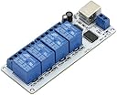
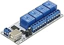
SainSmart USB 4 Channel DC 12V Relay Module Automation for Arduino Raspberry Pi DSP AVR PIC ARM
Product ID: 4103638
Details
- BrandSainSmart
- Connector TypeUsb
- Contact MaterialCopper
- Contact TypeNormally Open
- Mounting TypePlug In Mount
Desertcart purchases this item on your behalf and handles shipping, customs, and support to Seychelles.
Overview: This USB Relay Controller/Data Acquisition Module allows computer controlled switching of external devices as well as full bi-directional communication with the external world (ideal for Data Acquisition applications) using the USB port of your computer. The controller is very flexible and can be used in many custom applications including weather stations as well as temperature monitoring, logging and control as it can be easily connected to temperature and other types of sensors.Communication Parameters: 8 Data, 1 Stop, No Parity Baud rate : 9600 Drivers are available to work with the following operating systems: Windows Server 2008 R2, Windows 7, Windows 7 x64, Windows Server 2008, Windows Server 2008 x64, Windows Vista, Windows Vista x64, Windows Server 2003, Windows Server 2003 x64, Windows XP, Windows XP x64, Windows 2000, Windows ME, Windows 98, Linux, Mac OS X, Mac OS 9, Mac OS 8, Windows CE.NET (Version 4.2 and greater) Commands: FIRST channel commands: OFF command : FF 01 00 (HEX) or 255 1 0 (DEC) ON command : FF 01 01 (HEX) or 255 1 1 (DEC) SECOND channel commands: OFF command : FF 02 00 (HEX) or 255 2 0 (DEC) ON command : FF 02 01 (HEX) or 255 2 1 (DEC) THIRD channel commands: OFF command : FF 03 00 (HEX) or 255 3 0 (DEC) ON command : FF 03 01 (HEX) or 255 3 1 (DEC) FOURTH channel commands: OFF command : FF 04 00 (HEX) or 255 4 0 (DEC) ON command : FF 04 01 (HEX) or 255 4 1 (DEC) Download: https://s3-ap-northeast-1.desertcartaws.com/sain-amzn/20/20-018-909/20-018-909.rar Review: Cheap. Works perfect for my purpose. - I have a virtual pinball cabinet, and I wanted to add a relay to control a fan for the "Whirlwind" game. I didn't want to spend a lot of money on this silly project. The reviews are so poor but I figured I'd risk it. There's a C# sample that Anthony Marshall provided, and it worked on this board out of the box. [...] I modified this to work in the pinball simulator's framework interface, and bam! My fan kicks on when the storm hits! I checked the other 3 relays and they work fine as well. The only negative is that the relays click a few times during boot up, apparently some issue with the FTDI chip. Sainsmart notes this in the product description on their site. Overall it's exactly what I was looking for. Review: Once this was done and I found an old 5 volt dc wallwart from a discarded switch this board works great. Pity the documentation - Step one download the VCP (Virtual Comm Port) driver from (xxx).ftdichip.com/Drivers/VCP.htm. After installing driver, plug in the usb cable and the board will be identified as a comm port. Use device manager to determine comm port #. Open comm port at 9600 baud, 8 bit, no parity, 1 stop bit no flow control. Mr. Merryman was correct in his command determination. The relays are selected by binary where: 0001 = relay 1 on = Dec 1 0010 = relay 2 on = Dec 2 0100 = relay 3 on = Dec 4 1000 = relay 4 on = Dec 8 Let relayvalue = decimal value of relay desired ie: relayvalue = 1 for relay one. Then send chr$(relayvalue) to the comm port. If you want multiple relays add their decimal values together, 1 & 4 would be relayvalue=9 To then turn relay 4 off, subtract 8 from relayvalue and send relayvalue=1, turning off relay 4 and leaving relay 1 on. Once this was done and I found an old 5 volt dc wallwart from a discarded switch this board works great. Pity the documentation is lacking.
| ASIN | B009A5246E |
| Best Sellers Rank | #4,331 in Single Board Computers (Computers & Accessories) |
| Brand | SainSmart |
| Brand Name | SainSmart |
| Coil Voltage | 12 Volts |
| Connector Type | Usb |
| Contact Material | Copper |
| Contact Type | Normally Open |
| Customer Reviews | 3.6 out of 5 stars 28 Reviews |
| Manufacturer | SainSmart |
| Maximum Switching Voltage | 12 Volts |
| Minimum Switching Voltage | 12 Volts |
| Model | 101-70-117-03 |
| Mounting Type | Plug In Mount |
| Operation Mode | Automatic |
| Unit Count | 4.0 Count |
D**X
Cheap. Works perfect for my purpose.
I have a virtual pinball cabinet, and I wanted to add a relay to control a fan for the "Whirlwind" game. I didn't want to spend a lot of money on this silly project. The reviews are so poor but I figured I'd risk it. There's a C# sample that Anthony Marshall provided, and it worked on this board out of the box. [...] I modified this to work in the pinball simulator's framework interface, and bam! My fan kicks on when the storm hits! I checked the other 3 relays and they work fine as well. The only negative is that the relays click a few times during boot up, apparently some issue with the FTDI chip. Sainsmart notes this in the product description on their site. Overall it's exactly what I was looking for.
D**B
Once this was done and I found an old 5 volt dc wallwart from a discarded switch this board works great. Pity the documentation
Step one download the VCP (Virtual Comm Port) driver from (xxx).ftdichip.com/Drivers/VCP.htm. After installing driver, plug in the usb cable and the board will be identified as a comm port. Use device manager to determine comm port #. Open comm port at 9600 baud, 8 bit, no parity, 1 stop bit no flow control. Mr. Merryman was correct in his command determination. The relays are selected by binary where: 0001 = relay 1 on = Dec 1 0010 = relay 2 on = Dec 2 0100 = relay 3 on = Dec 4 1000 = relay 4 on = Dec 8 Let relayvalue = decimal value of relay desired ie: relayvalue = 1 for relay one. Then send chr$(relayvalue) to the comm port. If you want multiple relays add their decimal values together, 1 & 4 would be relayvalue=9 To then turn relay 4 off, subtract 8 from relayvalue and send relayvalue=1, turning off relay 4 and leaving relay 1 on. Once this was done and I found an old 5 volt dc wallwart from a discarded switch this board works great. Pity the documentation is lacking.
G**G
How to use this on Android
As others have said, the instructions and documentation really stink and the hardware has a few flaws. However, the comments on here really helped me to get this running reliably from an Android tablet. I'd like to add to the discussion to make this easier for the next person. Software: (1) You MUST set this to bitbang mode using the FTDI driver for your operating system. Specifically, for Android, I ended up passing FT_BITMODE_SYNC_BITBANG to the setBitMode method of ftDev. (See #3 below.) This cost me literally 4 hours of pulling my hair out. (2) The instruction set that Thomas Merryman posted is correct. You're writing a single byte with 0-F to the device to change the relay states. The product documentation is completely incorrect - ignore it completely. (3) To get going on android, I used a project called "Android Java D2XX". I'd put the URL, but Amazon would scrub it out. Google for the following and you should find it: "Android Java D2XX - Example projects to connect FTDI peripheral devices to an Android Host with the Java D2XX driver". For troubleshooting while getting up and running, the specific file that I modified to mess around with was DeviceUARTFragment.java, and specifically the SendMessage method. I modified that method to (1) set to bitbang mode (it is NOT in bitbang mode by default which tripped me up big time) and (2) convert the input from the app's UART screen (called writeText) to a byte (rather than a byte representation of a string of ascii chars). Then you can install the app on your Android device and use the UART GUI to write 0-15 and see the corresponding relay state changes. Hardware: (1) The circuit does not dissipate the voltage transient from opening a relay on a high inductance device (like a high power solenoid ... which I am using). You can overcome this by soldering on a freewheeling diode for each relay. Turn the board over - solder diodes from the "outer" pins surrounding the u-shaped holes. The diodes direction matters - it should point towards the USB port. (2) You can power the relays from the USB port by adding a jumper wire. Connect one end of the wire to the VCC terminal block then push the other end of the wire through the hole labeled 5V (just under R10), turn the board over and solder in place.
N**R
Worthless without much better documentation.
I've spent an entire day trying to get this to work attached to a machine running Linux. The "documentation" consists of: A short word document consisting mostly of screen captures of a windows utility to turn the relays on or off. A jpeg with the same information about baud and hex codes as on the Amazon description page. You would think that you could just fire up a terminal program and write the hex values to the serial port. For that matter: echo -en '\xFF\x01\x01' > /dev/ttyUSB0 Should work if the baud rate is correct. They also include several datasheets for the FTDI on which this is based. This chip has thousands of different applications so parsing out what if anything applies to this application is difficult. If you look hard enough there's a wiki page for this product: [...] It mentions software code examples for several languages, but doesn't have any. Here's a more convenient link for the "documentation" frmo the wiki page. [...] Aside from cheap terminal blocks with non-captive screws, the rest of the hardware looks solid enough. I'd give it several more stars if I could get it to work.
L**E
Five Stars
Product is just what was ordered.
A**R
Here's how they work
If you're trying to use these on Mac OS X or Linux, you'll probably be disappointed. These use the BITBANG mode of the FTDI chip. This is a little-used feature of the chip that lets you turn on and off GPIO pins on the device. Also afaik it needs to be accessed using the D2XX drivers which, though they kinda exist for Mac OS X and Linux, aren't easy. So this device is plug-and-play in Windows, but it's plug-and-curse-for-a-few-hours everywhere else.
I**R
Very good hardware design - 4 Stars. No documentation, even on web - 1 Star.
The device works well, but is shipped with zero documentation. Some of the comments appear to be inaccurate. I finally got it to work with a VB.Net program I wrote. The method that worked used and FTDI supplied DotNet library and a "bit banging" mode from that library. Once written, the device works great and I have already bought more.
S**G
Five Stars
Awesome
J**.
Great product for the price
Everything was as described. Great product for the price.
Trustpilot
2 weeks ago
2 weeks ago