


Desertcart purchases this item on your behalf and handles shipping, customs, and support to Seychelles.
⚡ Power your smart home with instant WiFi relay control — don’t get left offline!
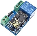
The HiLetgo ESP8266 5V WiFi Relay Module integrates a powerful ESP8266 WiFi chip with a 10A relay, enabling remote switching of high-current devices via mobile app control. Designed for smart home automation, it supports up to 5 simultaneous client connections in access point mode, is PCB-mountable, and meets CE and FCC standards. Ideal for professionals and DIY enthusiasts looking to add reliable, wireless relay control to their IoT projects.
| ASIN | B071LMSLRW |
| Best Sellers Rank | #866,143 in Tools & Home Improvement ( See Top 100 in Tools & Home Improvement ) #943 in Electrical Outlet Switches |
| Brand | HiLetgo |
| Brand Name | HiLetgo |
| Coil Voltage | 5 volts |
| Connector Type | Through Hole |
| Contact Current Rating | 10 A |
| Contact Material | Silver |
| Contact Type | Normally Open |
| Current Rating | 10 A |
| Customer Reviews | 3.6 out of 5 stars 52 Reviews |
| Manufacturer | HiLetgo |
| Maximum Switching Current | 10 A |
| Maximum Switching Voltage | 30 volts |
| Minimum Switching Voltage | 30 volts_of_direct_current |
| Model | 3-01-1409 |
| Mounting Type | PCB Mount |
| Number of Terminals | 2 |
| Operation Mode | Automatic |
| Part Number | 3-01-1409 |
| Specification Met | CE, FCC |
| Unit Count | 1 Count |
| Wattage | 50 watts |
R**G
good relay board for IoT projects
This is a review for ESP8266 5V WIFI Relay Module. It is a small unit that allows you to control a relay switch remotely. The main components of this board is esp8266, STC15F104 and of course a relay switch. There isn't much documents available. After some research online, I finally manage to get enough information to make the switch working. 1) You need a 3.3V FTDI converter connect to this module. The FTDI TX pin goes to the RX pin of the module and the FTDI RX pin goes to FTDI TX pins of the module. Finally, connect FDTI GND to the module GND. You also need an external 5v to power up the module board. The purpose of this FTDI connection is allowing you to start a ESP8266 server at TCP port 8080 Enter the following commands to activate the server (i.e. I used Arduino serial monitor as my serial terminal, the baud rate was to 9600) AT+CIPMUX=1 AT+CIPSERVER=1,8080 2) You also need an Android app to control the relay. For me I use an app called "Wifi Controller" but I think other app should work as well. 3) Open your phone wireless setting, you should see an SSID named "AI-THINKER_XXXXX". You can go ahead and connect to it. By default, the esp8266 ip address is 192.168.4.1. Once you are connect to the esp8266. You can send the following HEX vales to control the rely (see my video demo). send A0 01 01 A1 will turn off the relay send A0 01 00 A2 will turn on the relay Note that you will need to redo step 1 if the power of the rely board is loss. I am still searching if there is a way so that the board will start the server automatically when it is on. Also how to use this module on a IOT project. However, this is beyond the scope of this review. Anyhow, I would recommend this board if you want to learn more about ESP8266, relay switch or IoT projects.
P**N
Not impressed
As other reviews indicate, the chinglish documentation is rather awful. My use-case for this unit was with my own code on the ESP8266-01 controlling a relay. I liked the form-factor indicated and really didn't need much documentation; the price point was ok so I took a chance. Note if you go to the web-site indicated on the unit, not only do you get a Chinese only insecure web-site (slow when accessed from the US) but all the information/writing is in images (perhaps scrabed from other sites?). Using my camera to translate, and it more or less sounds exactly the text that's hard to understand on Amazon (and the link someone kindly linked to create.arduino.io). In other words, it looks like purposely very little information about this unit. The contact information on the web-site doesn't match the website domain - a lot of warning signs about trust and reliability. And it looks like the unit is single purposed even though it's based on an ESP8266 that every maker out there know how to program. I probably will end just grabbing the relay and perhaps the regulator from this board and trashing the rest. Note, I really appreciate that the unit comes with a pre-programmed ESP8266-01 but that code is as insecure as it gets. It's a no-go. There's no option to just power it up and configure it via a phone, and you have simple commands, no state no nothing, so this really is just a toy. For that, it's fine. But doesn't fit my use-case. First big problem - there's no way to pull D0 to ground to allow for programming! My unit has 3 "extra" pins where one claims to be RST (doesn't reset when pulled low). Really would have been better with a push-button for that. And if it's supposed to be FTDI compatible (not without pulling D0 to GND it won't be) that RST should be connected to RTS to allow it to reset the unit correctly after programming. So bottom line, you need to program your unit "else-where". And if that's the case, I can test the unit "else-where" and there's no need for FTDI pins at all. Or better, add a usb interface on the empty underside and avoid people struggling with voltages. As other reviewers have pointed out, there's a second micro-processor (N76E003) on the board which makes little sense given the application. We're talking about a single "on/off" output and the ESP8266 comes with two pins that works just fine in the standard setup. Heck, they have to use one of them to communicate with the other microprocessor! The reasons a second processor is there can only be cause of undocumented features which disqualify the unit. I really like the 3.3v of the ESP8266 so the 5v requirement pushes me the wrong way here. I need to provide 5v to just have it regulated down and at the same time it's not clear if the FTDI lines should follow the ESP8266 3.3v or 5v? I see no mosfet translation of the voltages, so that probably explains why mine is running relatively hot on this unit. The board says 5v on the VCC so you would asume the TX/RX would be 5v too (and if you set your FTDI to 3.3v it's VCC line is 3.3v too!). This would really have been so much simpler if they just used a 3.3v triggered relay instead. To do this on my own all I need is add my own 110v->3.3v regulator, get a proper 3.3v triggered relay and I should use less power and gain full control of programming, setting up OTA and ensure SSL is implemented communicating with the unit. It means I can have the state recorded in NVRAM so if power goes out, the unit can come back to the same state it was before the power went out (or use a latching relay). Perhaps using this board as an inspiration for a compact layout would be the biggest value from this unit. Not sure yet. So if you just want to write serial commands and see a relay being controlled, this is a nice small board for it. But you can do this very simply with a breadboard and a relay already (just use a 3.3v relay). Add a protection diode to avoid feedback from the coil, and you're golden. D0 or D2 then connects directly to the coil, or if you're the careful kind through a simple NPN transistor/mosfet. And now you're in charge of what causes the signal to be turned on/off.
J**B
I like it now that I can control the relay.
I did not like that it was not a simple GPIO output to control the relay from the ESP01. The ESP must be running the AT command firmware. OK, but not good for me. I need a blank ESP01. This relay has a second MCU to control the relay, It is listening on the ESP01 TX/RX. Here is the code to open and close the relay. #include "Arduino.h" byte RlyOpen[] = {0xA0, 0x01, 0x00, 0xA1}; byte RlyClose[] = {0xA0, 0x01, 0x01, 0xA2}; void setup() { Serial.begin(9600); } void loop() { //Open the Relay Serial.write("+IPD,0,4:"); Serial.write(RlyOpen, sizeof(RlyOpen)); Serial.println(""); delay(5000); //Close the Relay Serial.write("+IPD,0,4:"); Serial.write(RlyClose, sizeof(RlyClose)); Serial.println(""); delay(5000); }
H**S
Relay does not work
The Wi-Fi module works as it should, but the relay does not work when using either GPIO 0 or GPIO 2.
C**F
Been looking for this for a long time!
Daddy loves new toys! I am working on an application to turn on my water pumps during torrential rains. I want to have the pump ready to go, but don't want to risk electrocution or getting wet to go outside and turn it on. With this module, I don't have to. My family can connect to this device, and turn it on or off via our cell phones! Now, I need to figure a way to trigger it with SMS codes, so I can turn it on remotely. About the item: This item shipped quickly. The photo does not do it justice, but look at the workmanship! It is in excellent condition. This will easily fit inside the waterproof electrical housing I use.
T**I
Not a simple ESP8266 unit: Has a IO Coprocessor
The relay is not controlled by the ESP8266, the two IO lines on the ESP8266 are not connected. The relay is connected to a STC Microcontroller which is connected to the ESP8266 serial lines. This means that this device is hard to reprogram, as the module can't be reprogrammed in situ as the other MCU interferes with the serial communications, and even if you do reprogram it you then need to know the command set for that other IC. (Other posters have figured that out, but still.) The firmware didn't work out of the bag. It launched the usual 192.168.4.1 AP but when I connected to it nothing loaded. There's other ESP8266 modules available that just use IO0 to control the relay, use one of them. There's no need for a coprocessor in this application.
D**N
Cannot program
Cannot program the ESP-01, in another relay via FTDI or a dedicated USB programmer.
L**Z
Open door garage
Excelente para uso en open door garage en la frequency 2.4Ghz atravez de una aplicación de Google play... Attention esta aplicación de Google es poco comfiable dado que contiene publicidad y quizás sea usada para fishing de tus datos personales tenlo siempre presente.
Trustpilot
2 weeks ago
3 days ago